Punch Definition
This function provides a method to efficiently define the various blanking punches that will define the Blank shape. The function uses a single part to produce a truncated strip layout - You can also create an identical mirror of the part.
Important: Only one instance of this function is available in a Die Quote. If the function is used again, it will edit the existing feature.
In this function you can create blanking curves and punches. The defined data is collected, processed, and loaded into the Die Quote.
Requirements
- Single Part
- Mirror of this part must be identical
- Part Nesting step successfully completed.
- Strip Dimension step successfully completed.
- The carrier and webs and other components that are to be used in the strip to be quoted must be successfully defined before running this function.
Process
-
Click the button in the menu on the right hand side of the graphics pane to open the function. The Feature Guide is shown here:
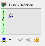
Tip: You can open the Feature Guide at any time by right-clicking the mouse in the graphic display area.
Required Step 1
 : Pick entities for the composite curve.
When you open the function, the environment is configured with the available tools. Any other parts are hidden and the Strip Part.elt file is activated and the top view is displayed. You can only work with curves in this environment.
The Sets pane is displayed below the Feature Tree.
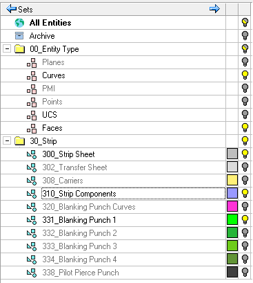
A Set is a group of entities. Any sets already defined in the part file will be deleted. There are two criteria sets defined for single color and faces. The part curves available for selection are added to the Curves set.
Note: You can define a set by selecting specific entities and declaring that they are part of a specific set (Selection Set) or by declaring that all entities that have specific characteristics (for example, all red lines) are included in a specific set (Criteria Set). These two types of sets cannot be mixed. Each set is either a Selection or a Criteria set, for more on Sets, see Sets.
-
Required Step 1: Define the curves that will be used to create the punch curves.
-
Select a closed contour that was created in the Strip Sketcher (by selecting a closed and planar composite curve) in order to define the punch.
The parameters are shown here:2D Single Indication / One by One / Chain
2D-Single Indication Create a contour by using a single indication (close to screen or close to face).The system finds a closed loop from all displayed edges/curves lying in the defined plane (up to the defined tolerance). (default) Chain
Create a contour by picking a curve, a direction, and then the last curve in the chain. The shortest possible chain connecting the two curves will be selected to create the contour.
One by One
Create a contour by picking individual curves.
Max Gap
This is the maximum gap allowed between the selected geometries, when joining them into a single geometry. If the gap between the selected geometries is greater than the Max. Gap value, they are treated as separate geometries.
Composite
Create a composite curve (not editable).
Without Simplify
Do not simplify the result to reduce the number of edges (not editable). XY Active
The composite curve is on the default XY Active plane (not editable). No Planar Approximation Keep last
Curves that are completely covered by the created composite curve are removed. When this option is selected, the last section in the composite curve is kept.
The first two blank stations are displayed (the remaining stations are temporarily hidden) and you are prompted to pick a point (Single Indication) to create the closed contour.
The system finds a closed loop from all displayed edges/curves lying in the defined plane (within the specified tolerance). -
In the Sets pane, click the Set you want to assign the selected contours to. Inappropriate sets are displayed in grey and cannot be selected.
-
Repeat the selection and assignment steps as often as required.
-
-
Click OKOK
 or ApplyApply
 in the Feature Guide to complete the function.
 The function will perform a series of operations:
-
Curves will be created and will be added to the single-color set named Blanking Punch Curves.
-
A bounded face will be created from the composite curve and placed on the single-color set named Blanking Punch 1. You can use any of the four Blanking Punch sets (1-4) to change face colors for better visualization.
-
-
Click OKOK
or ApplyApply in the Feature Guide to complete the function.The function checks the Blanking Punch x sets. If there are no curves present, an on-screen dialog alerts you that there are no blanking punches defined.
-
If this is intentional, click OK to submit the information to DieQuote.
-
If blanking punches are required, click Exit to go back and assign curves.
The function processes the defined blanking punches and calculates the data using the criteria in the following table.
SETs list
Data Block Parameter
Calculation
Blanking Punch Curves
Blank– Punch Qty
Total # of groups
Blanking Punch Curves
Blank – Metal Forming Size
SUM of all the perimeters of all the groups
-
-
A notification is displayed when processing is complete. Click Exit
 to move to the next step.
