Nesting 
This group of functions enables you to place the blank forming shapes into the strip and organize them in a layout manner. Using this option you can control the utilization of the strip by arranging the blanks in the most efficient way.
The nesting operation will use the Blank’s most outer contour, independent of the way it was created to allow you to leave excess material beyond the calculated blank, for accurate trimming at later stage, deep forming operations, or to shift wrinkles caused by forming operations outside the part
Parts that have been blanked can be quickly mirrored and nested within the One Part option.
Important: Only one instance of this function is available in a Die Quote. If the function is used again, it will edit the existing feature.
Requirements
- Single Part
- Any mirror of this part must be identical to the original

- The Die Skin function successfully performed (a Blank part or contour must have been created).
Process
-
Click the button in the menu on the right hand side of the graphics pane to open the function.
This function does not have a Feature Guide. When you open the function, the environment is configured with the available tools. Any other parts in an Assembly are hidden and the part held in the cutting.elt file that is displayed in an Isometric view. You can only work with curves in this environment.
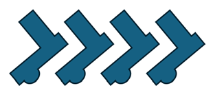
- Define the nesting parameters. The nesting preview displays the selected blank multiplied by four along the strip.
The first instance of the blank is placed so that its Work CS (Coordinate System) is on the active UCS of the strip sub-assembly. Additional instances of the first shape are shown spread in the X direction of the active UCS of the strip sub-assembly, so that the distance in the X direction between every two parts is the Min. Distance. The blanks are displayed bounded by bounding box lines.
The following parameters are initially displayed:
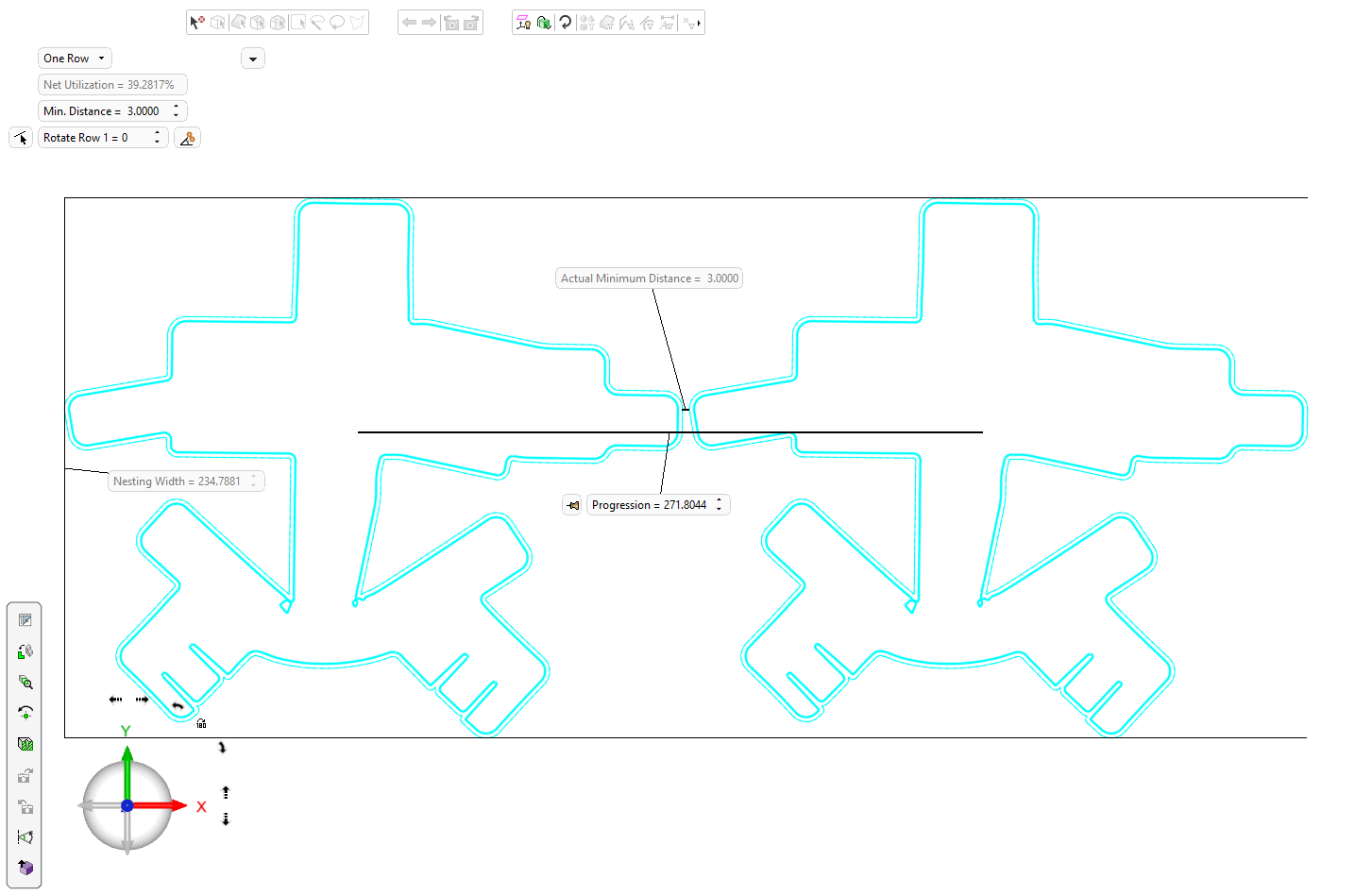
This is a dropdown selector used to define nesting of the part on one or two rows.
One Row
Nest the part on one row
Two Rows (Same Part)
Nesting the part on two rows. The selected blank duplicated along the strip.

The first two instances of the blank (the first instance on each row) are placed so that their Work CS's are shifted to +/- Y direction with reference to the active UCS of the strip sub-assembly. The Progression value remains as it was in one row. The shift in the Y direction conforms to the Min. Distance value.
The additional instances of the blank are spread in the X direction of the active UCS of the strip sub-assembly, so that the distance in the X direction between every two parts is the Min. Distance.
Two Rows (Part and Mirror) Copy and then mirror the selected blank (relative to the XZ plane). The net nesting utilization according to the selected shape and parameter settings. This parameter is system calculated (read only) and is the ratio between the area of the blank (the gross area including holes) to the strip area (in percentages).
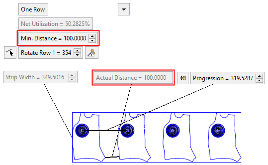
The minimum distance between the nested parts.
The Actual Distance value between the parts cannot be less than this "Min. Distance" value.
Valid inputs are >= 0.If the Progression parameter is in Fixed mode (see below), the "Min. Distance" parameter is dimmed.
This parameter controls the rotation of the blanks around the Z axis of their Work CS. The default value is 0.
Rotate Part (row 1) controls the rotation of the blanks in row 1 around their Work CS;
When changing rotation value, the Progression parameter value changes to keep the defined minimum distance.
A Reference Line button
 is attached to this parameter. Pressing this button allows you to pick a reference line for rotation; the blanks will rotate so that this reference line is parallel to the X direction. The reference line can be selected from linear edges/curves from any component in the assembly. In addition, 2 points can be also selected for the direction (selected from any component in assembly file). The rotation angle is displayed in the "Rotate Row" parameter. The angle is not associative to the reference line.
Note: Rotating when the Progression and/or the Strip Width parameter is Fixed, may cause overlapping of the blanks.
Note: Only visible if Two Rows (Part and Mirror) is selected.
This parameter controls the rotation of the blanks around the Z axis of their Work CS. The default value is 0.
Rotate Mirror (row 2) controls the rotation of the blanks in row 2 around their Work CS.
When changing rotation value, the Progression parameter value changes to keep the defined minimum distance.
A Reference Line button
is attached to this parameter. Pressing this button allows you to pick a reference line for rotation; the blanks will rotate so that this reference line is parallel to the X direction. The reference line can be selected from linear edges/curves from any component in the assembly. In addition, 2 points can be also selected for the direction (selected from any component in assembly file). The rotation angle is displayed in the "Rotate Row" parameter. The angle is not associative to the reference line.Note: Rotating when the Progression and/or the Strip Width parameter is Fixed, may cause overlapping of the blanks.
Switch the upper and lower parts to transpose the rows
Note: Only visible if Two Rows (Part and Mirror) is selected.
Click this button to automatically find the optimal rotation angle that gives the best utilization rate of the strip.
-
For the One Row toggle option:
This button is displayed adjacent to the Rotate Part (row 1) parameter and finds the optimal angle for the best utilization rate for that row. -
For the Two Rows toggle option:
This button is displayed adjacent to the Rotate Mirror (row 2) parameter and finds the optimal angle for the best utilization rate for both rows.
The strip display and the angle in the relevant row parameter are updated accordingly.
Note: This button is only available when the Progression parameter is in a Float state (when the Float
 button is displayed adjacent to the parameter).
Toggle the parameters expand/collapse button
/ to display the following predefined nesting parameters: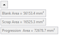
Blank Area
The blank area according to the selected shape and parameter settings.
Scrap Area
The scrap area according to the selected shape and parameter settings.
Progression Area
The progression area according to the selected shape and parameter settings.
This displays the width of the bounding box.
-
For the One Row toggle option:
This parameter is dimmed (read only). -
For the Two Rows toggle option:
This parameter is displayed with an attached Fix/Float button ( /). By default, the Float button is displayed. When the Strip Width value is manually changed, the Fix button is displayed. This means that the width value is not associated with the other parameter values (for example, a change in the Min. Distance will not affect the Strip Width value).
To activate the parameter, toggle the Fix button to Float. The preview will jump to comply with the change.
This displays the actual distance between the blanks. This value is governed by the Min. Distance parameter value; the Actual Distance value can be greater than the Min. Distance value (depending on, for example, a manually changed Progression parameter value), however, it cannot be less than the Min. Distance value.
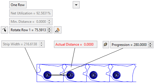
If blank overlaps occur (as a result, for example, of a manually changed Progression value), the "Actual Distance" parameter is shown as 0 and displayed in red.
This displays the distance between the blank's Work CS’s according to the Min. Distance. This value can be changed, with the preview changing automatically.
A Fix/Float button (
/) is attached to this parameter; by default, the Float button is displayed.When the Progression value is manually changed, the Fix
button is displayed. This means that the Progression value is not associated with the other parameter values (for example, a change in the Min. Distance does not affect the Progression value).To activate the parameter, toggle the Fix button to Float. The preview will jump to comply with the change.
This parameter is displayed when the Two Rows toggle parameter is selected.
This parameter controls the vertical distance between the two rows of blanks on the strip. A negative value can be entered.
This parameter is displayed when the Two Rows toggle parameter is selected.
This parameter controls the horizontal distance between the two rows of blanks on the strip. A negative value can be entered.
-
- Click OKOK
 or ApplyApply
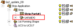
 in the Feature Guide to complete the function. When completed, the new Part appears in the Feature Tree