Die Skin
Create a skin (with no thickness) from an object. This enables clear and easy analysis of operations in the system.
Important: Only one instance of this function is available in a Die Quote. If the function is used again, it will edit the existing feature.
Note: The DieTip CS function must be successfully performed before this function can be used.
An example is shown in the following images:
|
Solid body before creating the skin |
The skin result |
|
|
|
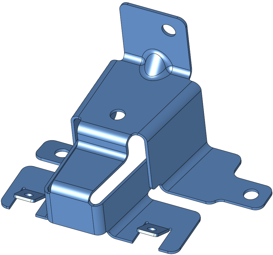
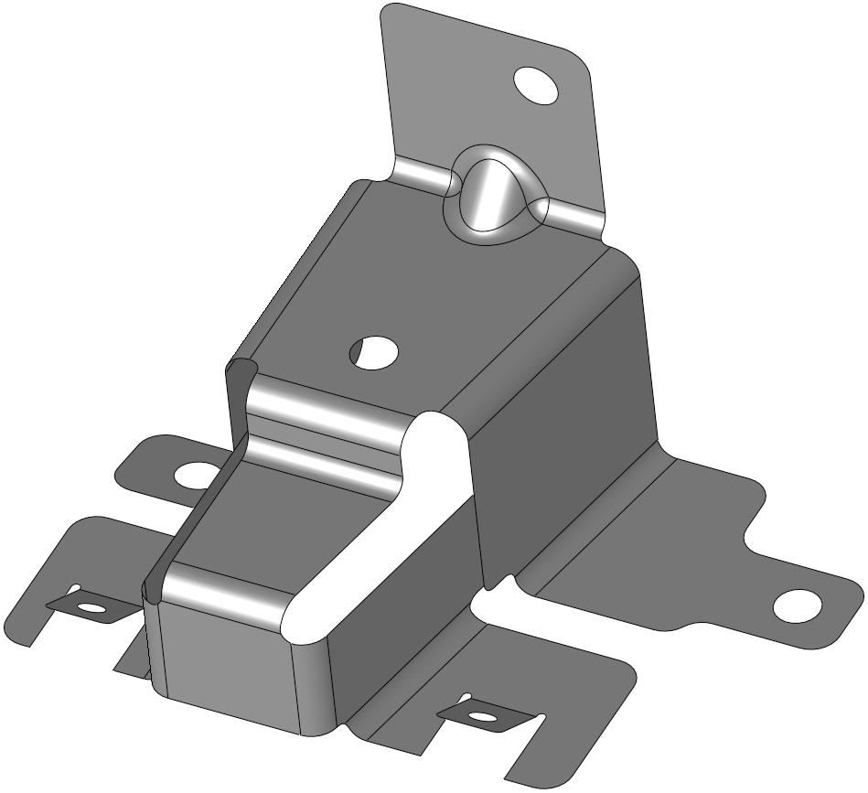
This feature highlights which faces will be removed. By default, all faces on the part are selected for deletion. You must pick the face that will be retained as the Die Skin.
Requirements
- Single Part containing geometry
- DieTip CS step successfully completed
Process
- Click the button in the menu on the right hand side of the graphics pane to open the function.
The Feature Guide is shown here.
The function will activate the top part in the Die Operations sub-assembly.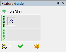
Tip: You can open the Feature Guide at any time by right-clicking the mouse in the graphic display area.
Required Step 1:
-
All faces on the part are initially selected for removal, you must pick faces on the solid object to deselect them. The faces you pick will be used to create the die skin. Selected faces are deleted.
Note: If you run the Die Skin without running the DieTip CS function, the following alert is displayed (this is not shown if you re-run the function).
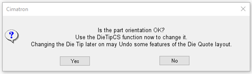
There are several factors that must be considered when deciding the part orientation, such as material usage, punch accuracy, burr locations and extruded holes, as well as how the part will be carried through the die, and how the part will exit the die. You should be aware of these when creating the quote data.-
If the part orientation is correct, click Yes.
-
To edit the part orientation, click No and re-run the DieTip CS function.
All faces are automatically selected for deletion.
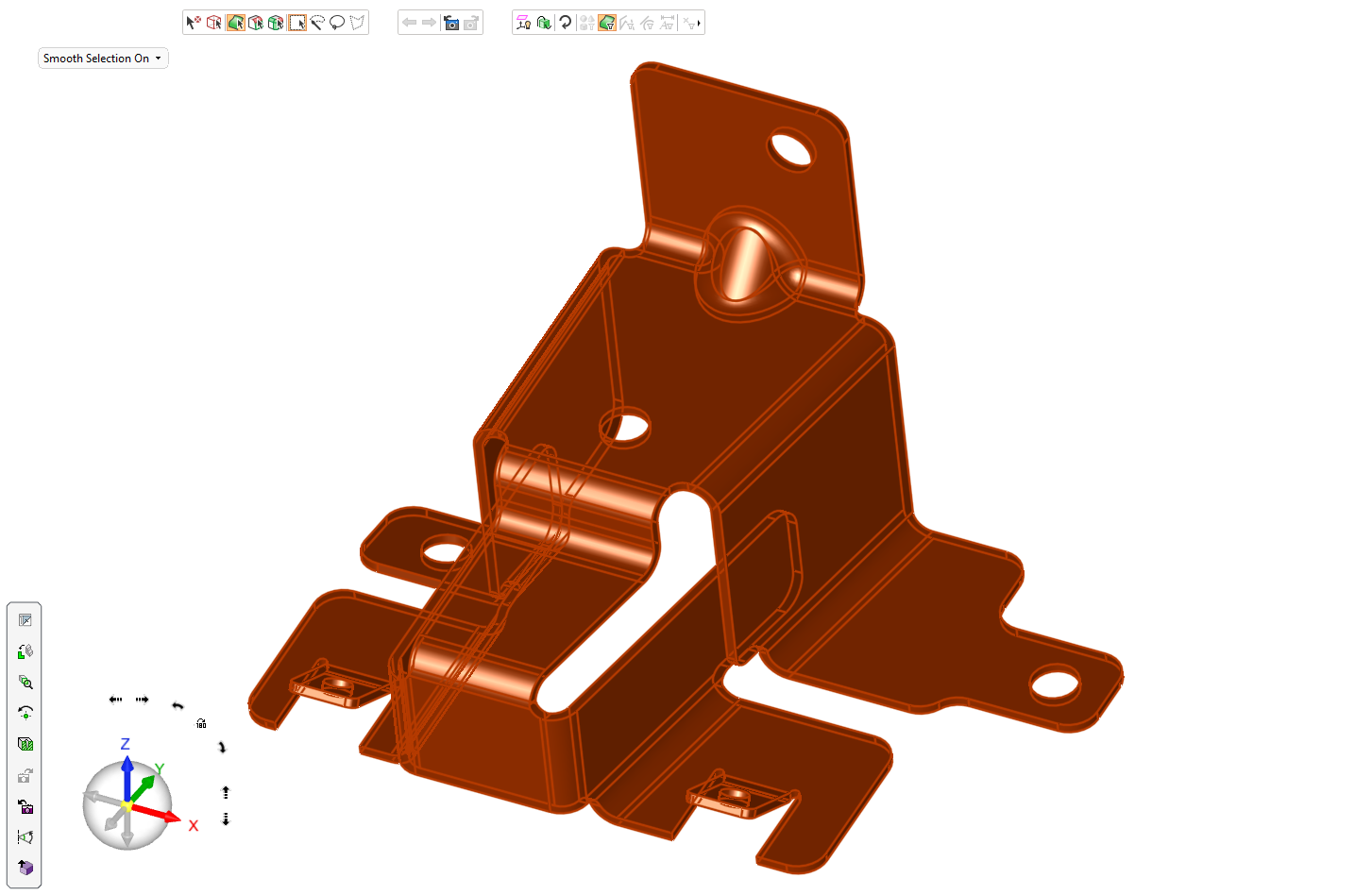
You must deselect the faces you do not want to delete.
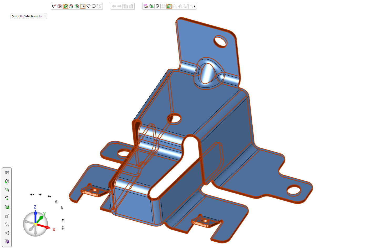
The following parameters are available:Smooth Selection
Smooth Selection On: Automatically select all smooth faces.
Smooth Selection Off: Pick individual faces.
Material Thickness Use the up and down arrows to select the required Die Skin material thickness value - default 2 mm (All measurements are displayed in metric values)
-
-
Click OKOK
 or ApplyApply
 in the Feature Guide to complete the function. The system creates five new part files in the Quote Data/Die Operations sub-assembly.
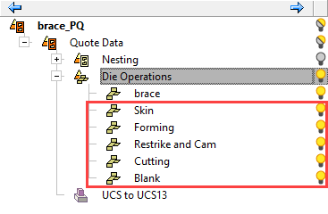
These are displayed in the X direction at an automatically determined progression distance.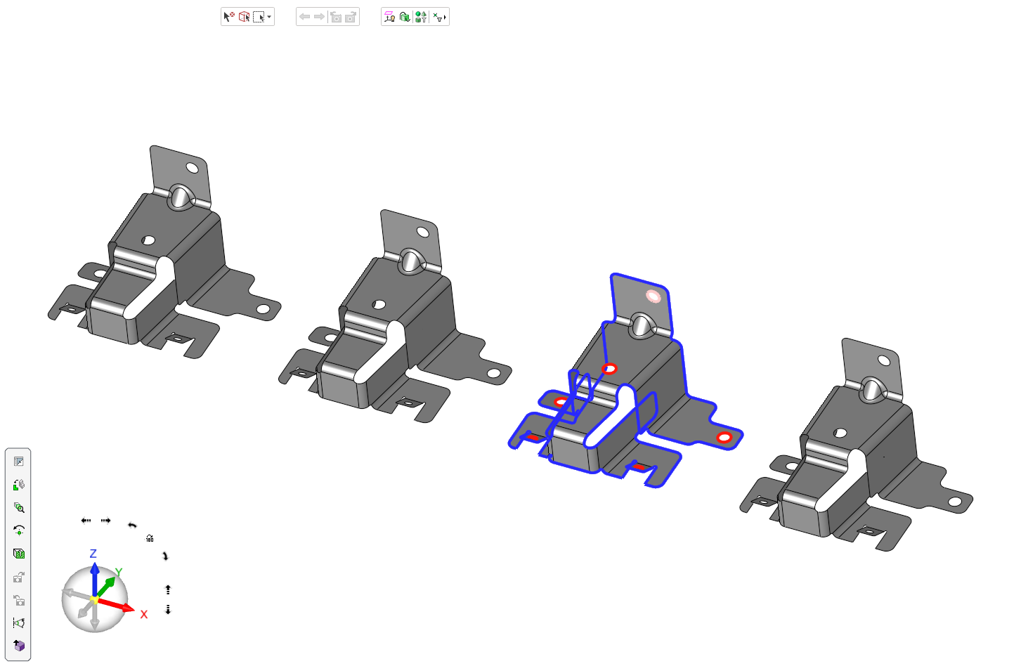
These files are ready for use in the subsequent Forming, Restrike and Cam, Cutting, and Blank processes. The Cutting set is processed using the Composite - Faces Outer Boundary and Close Open Gaps functions to identify the outer perimeter of the shape. -
When completed, the Die Skin feature will appear in the Feature Tree. The other copies of the original file are hidden to leave only the copy made for Die Skin operations visible, and you will be automatically transferred to the next stage of the wizard.