DieTip CS 
Create a DieTip CS (Coordinate System) on a forming shape. The DieTip CS is the master UCS for a forming shape part. The positioning of the parts in the forming shape assembly is defined according to this UCS.
The DieTip CS also defines the connection between the strip UCS (at certain stations) and the forming shape part when the part is added to the strip assembly.
This is the first stage that is performed when defining the forming shapes, and is described as the reference UCS (called DieTip CS) in the forming shape environment. Each part of the forming shape will contain a unique DieTip CS.
There are several factors that must be considered when deciding the part orientation, such as material usage, punch accuracy, burr locations and extruded holes, as well as how the part will be carried through the die, and how the part will exit the die. You should be aware of these when creating the quote data.
Requirements
- Single Part containing geometry
- UCS Normal to Plane step successfully completed
Process
Click the button in the menu on the right hand side of the graphics pane to open the function.
The Feature Guide is shown here:
|
|
Tip: You can open the Feature Guide at any time by right-clicking the mouse in the graphic display area. |
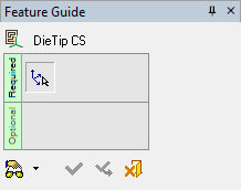
The procedure below describes how to first create the UCS by selecting three points and then define it as the DieTip CS. Before selecting the DieTip CS you must create the UCS based on existing points, as described in UCS by Geometry. This UCS will then be selected as the DieTip CS for the selected part, as described below.
-
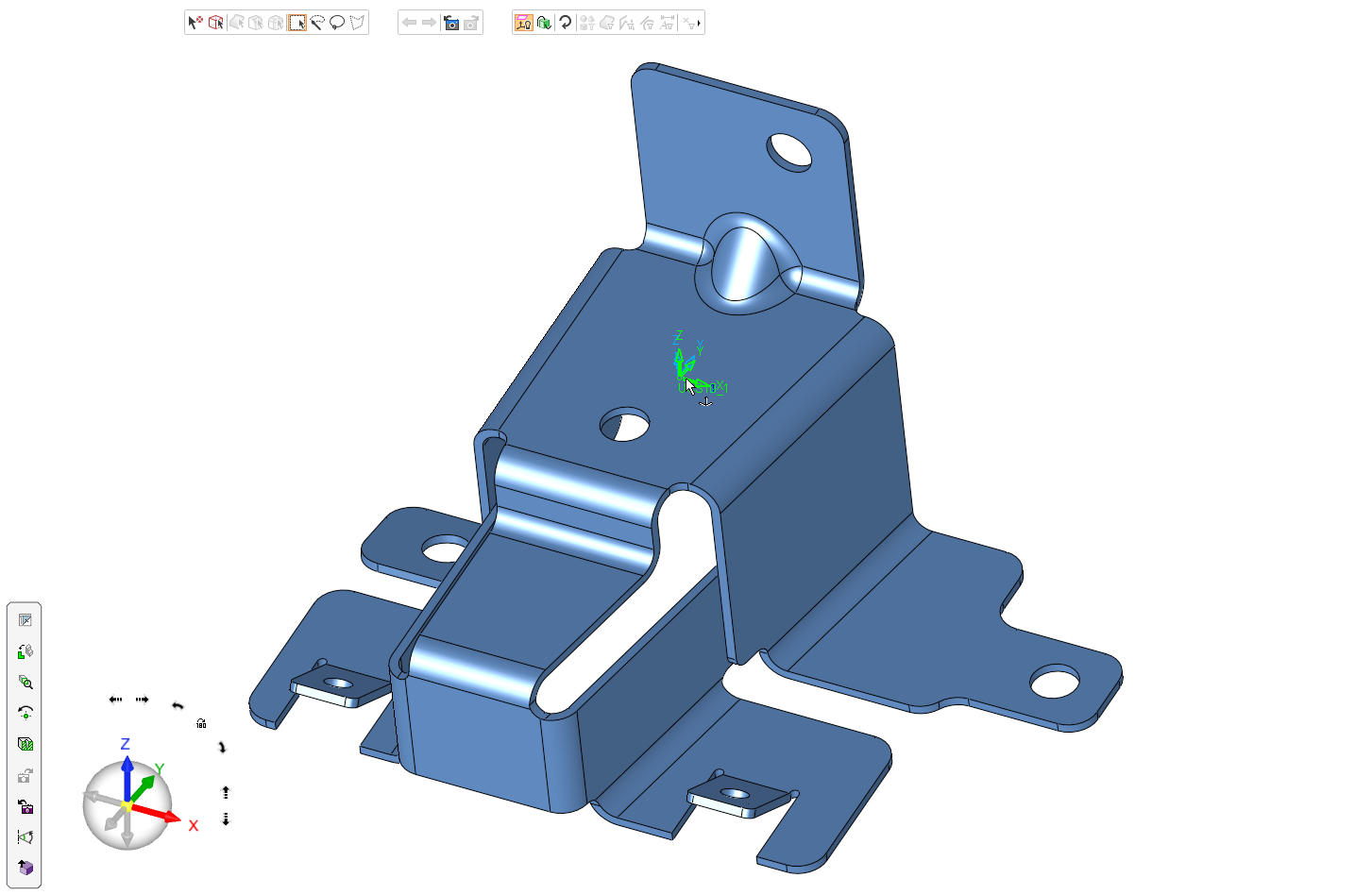
Select DieTip CS from the DieQuote menu and select the part UCS.
-
Click OKOK
 or ApplyApply
 in the Feature Guide to complete the function.
