Assign Cutting
This function provides a method to efficiently estimate the various Cutting Operations. The function allows you to specify a single part to produce a truncated strip layout - You can also create an identical mirror of the part.
Important: Only one instance of this function is available in a Die Quote. If the function is used again, it will edit the existing feature.
In this function you can mark the features that represent various cutting operations, including those that require CAMs (cutting operations that cannot be performed from the top and need to be done from the side). Select either curves and edges, or composite and sketch entities, and a color is applied to identify which cutting operation is to be performed (each color designates a different cutting operation). The available operations include:
- Shearing
- Blanking
- Slotting
- Lancing
- Nibbling
- Perforation
- Piercing
- Notching
- Trimming
- Deburring
The defined data is collected, processed, and loaded into the Die Quote.
Requirements
- Single Part
- Mirror of this part must be identical
- Die Skin step successfully performed (a Blank part or contour must have been created).
Process
- Click the button in the menu on the right hand side of the graphics pane to open the function.
The Feature Guide is shown here:
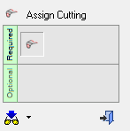
Tip: You can open the Feature Guide at any time by right-clicking the mouse in the graphic display area.
When you open the function, the environment is configured with the available tools. Any other parts in an Assembly are hidden and the part held in the cutting.elt file is displayed in an Isometric view.
-
Select the entities to assign as cutting edges in this environment. Optionally, filter the displayed entities to show curves and edges, or composite and sketch entities.
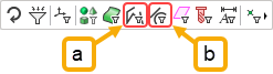
- Composite and sketch entities
- Curves and edges
-
The Sets pane is displayed below the Feature Tree.
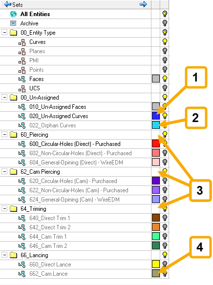
Features in the Cutting Sets pane
- Unassigned Curves
- Orphan Curves
- Assigned Curves (added to Criteria Set folders)
- Color Assignment
A Set is a group of entities. Any Cimatron sets already defined in the part file will be deleted. There are two criteria sets defined for single color and faces. The part curves available for selection are added to the curves set.
Note: You can define a set by selecting specific entities and declaring that they are part of a specific set (Selection Set) or by declaring that all entities that have specific characteristics (for example, all red lines) are included in a specific set (Criteria Set). These two types of sets cannot be mixed. Each set is either a Selection or a Criteria set. For more on Sets, see Sets.
-
Cimatron will automatically assign cutting operations to edges it can identify. Define the curves that will be added to each cutting operation by assigning a color to the part features. The paint tool is used to select edges, draw over an edge to select it. Select the curves that you wish to assign, and then click the required on-screen option for the set.
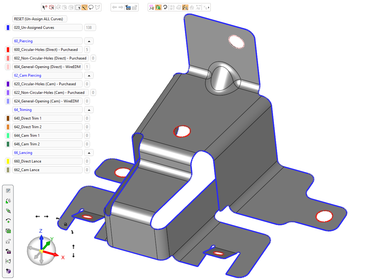
The color of the set you chose is applied to the curves, indicating which operation you want to run using that set of curves. Repeat the process to assign a color to each curve.
Curves can be re-assigned to a different set if required―Paint the curve to be reassigned and apply a different color.-
Curves that do not require a cutting operation should be assigned to the Un-Assigned Curves set. All curves must be assigned to one of the Cutting sets or to the Un-Assigned Curves set.
-
Multiple curves can be selected in one operation.
-
Click on individual curves to select. Shift-click a selected curve to de-select it.
-
Use the Select by BrushSelect by Brush
 option in the floating filter toolbarfloating filter toolbar
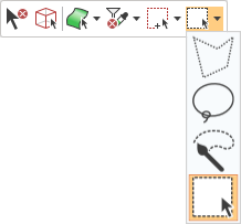 to select multiple entities by painting over the relevant area. Define the width of the brush by setting the Brush Diameter (displayed in an edit box under the brush icon on the Selection Toolbar).
 -
Use the Select by LassoSelect by Lasso
 option to draw a freehand selection border over the relevant area.
-
-
-
When you have assigned all the faces required for each operation, click the exit button
 in the Feature Guide. The function will perform a series of checks:
-
Any curve that does not belong to either the Un-Assigned Curves set or any of the Cutting sets (Piercing, CAM Piercing, Trimming, Lancing, and so on) is assigned to the Orphan Curves set and given the appropriate color.
If you have orphan curves, a dialog will be displayed. You must exit and restart the function, define the cutting type of these curves, delete them, or make them unassigned. -
If all the curves are in either the Un-Assigned Curves set and in one of the Cutting sets, an onscreen dialog is displayed to alert you that not all the curves have been assigned.
-
If this is intentional, click OK.
-
If additional cutting operations are required, click Exit to go back and assign curves.
-
-
If all the curves are in the Un-Assigned Curves set, there are no cutting operations to perform, and an on-screen dialog is displayed.
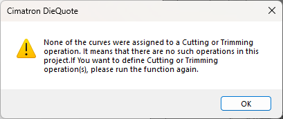
-
If no cutting operations are required, click OK.
-
If cutting operations are required, click OK and rerun the function.
-
-
-
The function processes ALL the faces in the Cutting Sets and calculates the data using the criteria in the following table:
SETs list
Data Block Parameter
Calculation
ALL: Trimming, Lancing (6)
Trims – Punch Qty
Total sum of all groups
ALL: Trimming, Lancing (6)
Trims – Metal Forming Size
Total sum of all curve lengths
ALL: Piercing, CAM Piercing (6)
Punched Holes – Punch Qty
Total sum of all groups
ALL: Piercing, CAM Piercing (6)
Punched Holes – Metal Forming Size
Total sum of all curve lengths
ALL: CAM Piercing, CAM Trim, CAM Lance (6)
Die Mount – Cam Qty
Total sum of all groups
ALL: CAM Piercing, CAM Trim, CAM Lance (6)
Die Mount – Cam Face Width
Total sum of all curve lengths
All Sets except Un-Assigned Curves and Orphan Curves
Blanked Openings – Metal Forming Size
Total sum of all curve lengths
-
A notification is displayed when processing is complete. Click Exit
to move to the next step.
