UCS By Geometry
Create a UCS by picking geometry (points and/or edges).
|
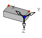
Pick the geometry |
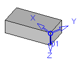
The new UCS is created |
|
|
|
Process
The following is the Feature Guide for UCS By Geometry.
|
|
Tip: You can open the Feature Guide at any time by right-clicking the mouse in the graphic display area. |
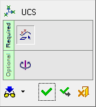
Required Step 1 
Pick the origin point and then points for the X and Y axes or pick an edge and a point.
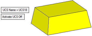
The following parameters are displayed.
|
UCS Name |
The name of the UCS being created. Click this parameter to edit the name. |
|
Activate UCS Off |
This is a toggle option Activate UCS On / Off, which enables you to activate (or not) the UCS being created. The default is ON. Note: In NC operations, the default is set in NC UCS Preferences (in the Activate Created UCS parameter). |
Points
Create a UCS by picking points to define the location and orientation of the UCS. The first point is the UCS origin, the second defines the +X direction, and the third defines the +Y direction.
-
Pick the first point to define the UCS origin.
-
The UCS preview is displayed, initially according to the orientation of the Interactive UCS.
-
Pick the second and third points to define the X and Y axes respectively. The UCS preview is now orientated as required.
Edge and Point
Create a UCS by picking an edge and a point. The edge defines the X direction, and the closest endpoint to the position where you picked the edge is selected as the UCS origin. Then pick a point to define the Y direction.
-
Pick an edge to define the UCS X axis.
-
The UCS origin point is automatically selected as the closet endpoint to the position where you picked the edge.
-
Pick a point to define the Y axis. The UCS preview is displayed.
Optional Step 1 
Rotate the UCS by entering the X, Y, and Z rotation values. The UCS is reorientated accordingly.
If the UCS creation is complete, click OK  or Apply
  in the Feature Guide.
When completed, the UCS feature will appear in the Feature Tree.
