UCS By Directions
Create a UCS by defining an origin point and two axes.
|
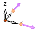
Pick the origin an 2 axes |
The new UCS is created |
|
|
|
General Interaction
The following is the Feature Guide for UCS By Directions.
|
|
Tip: You can open the Feature Guide at any time by right-clicking the mouse in the graphic display area. |
Required Step 1 
PickPick the point to define the location (origin) of the UCS, and then set any 2 of the 3 directional controls by vector.
The following parameters are initially displayed:
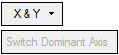
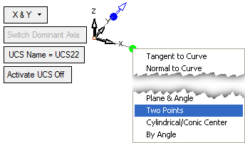
By default, the XY axes of the UCS are highlighted indicating you can re-define the vectors of these axes. For example:
- Pick a point.
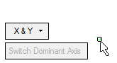
- The UCS is displayed with the default XY axes highlighted and additional parameters are displayed (see below for more information).
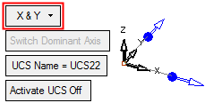
-
Use the X & Y dropdown list to select the axes to be highlighted (redefined).
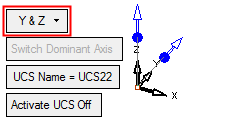
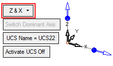
-
The following parameters are also displayed.
UCS Name
The name of the UCS being created. Click this parameter to edit the name.
Activate UCS Off
This is a toggle option Activate UCS On / Off, which enables you to activate (or not) the UCS being created. The default is ON.
Note: In NC operations, the default is set in NC UCS Preferences (in the Activate Created UCS parameter).
If you pick another point, the UCS origin is located on the picked point.
At this stage, you can select the directional arrows to change the vector of one of the highlighted axes. Pick the blue arrow base of the axis whose vector is to be changed, select the required option from the popup menu, and then pick the appropriate entities to define the new vector.
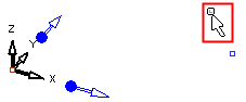
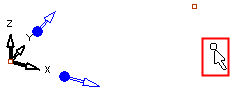
In the following example, the vector of the X axis is changed by using the option Two Points.
- The 1st point is selected.
-
The 2nd point is selected
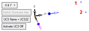
Note: If the 2 points were selected in the opposite order, the X direction would be as follows:
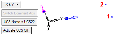
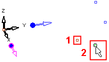
If required, you can change the vector of the same axis again (in this case X), or you can change the direction of another axis. If you change another axis, the Switch Dominant Axis parameter becomes available to enable you to define the dominant axis between the two changed axes. In the example below, the vector of the Y axis is changed by 2 Points as follows:
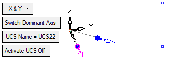
The result is as follows. The Switch Dominant Axis parameter is now available.
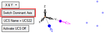
Select Switch Dominant Axis to define Y as the dominant axis. The UCS is changed to reflect this. Toggle this parameter as required.
Optional Step 1 
Rotate the UCS by entering the X,Y, and Z rotation values. The UCS is re-orientated accordingly.
Click OKOK or ApplyApply
 in the Feature Guide to complete the function.
