Setting a Direction: Plane and Angle
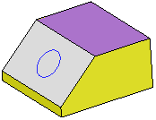
In the example below, the Add Extrude function is to be used to extrude the circle.
|
Extrude the circle. |
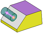
By default, the extrude direction is normal to the plane/face of the entity. |
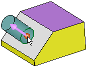
To select another direction, select the arrow base. |
A toolbar of direction options is displayed. For this example, select the By Angle option |
 |
|
|
|


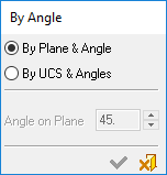
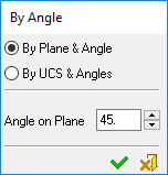
The By Angle dialog is displayed; select the By Plane & Angle option.
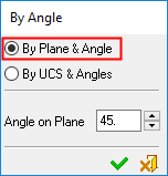
To set the direction vector, select a plane and define the angle.
|
Pick a planar face or plane that is parallel to the desired direction vector. |
A set of section and cross-section (C and S) axes appears. Enter the counter-clockwise angle from the S axis to the desired vector (180 degrees = no change in angle, but a flip in direction). |
||
 |
 |
||
|
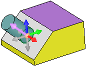
Result: In this case, an angle of 90 degrees from the S axis is set. |
Another view of the image on the left. |
||
|
|
|
|
|


