Body Integrity Analysis
Analyze various geometry quality issues of a selected B-rep object.
The Body Integrity function scans the part and highlights potential problem areas. Numerous integrity checks run simultaneously, and a concise chart presents the results. Different colors are used to highlight open, tolerant, and non-manifold edges on the part. Areas of self-intersecting solid or narrow knife regions are also indicated.
The Body Integrity dialog is displayed with predefined checks available for analysis.
|
|
|
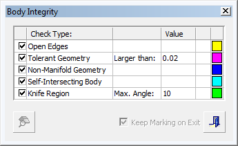
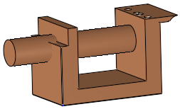
The Start AnalysisStart Analysis button is not available until at least one B-rep object is selected. Click on one or more B-rep objects to pick them, or drag a selection box around an area. The selection can be from different parts in an assembly.
Select the types of analysis checks that you wish to perform. By default, all the checks are selected. If no object is selected, or if all the checks are deselected, the Start Analysis button is grayed out and unavailable. For a description of each check type, see Analysis Options below.
Select the colors to be associated with each check.
|
|
|
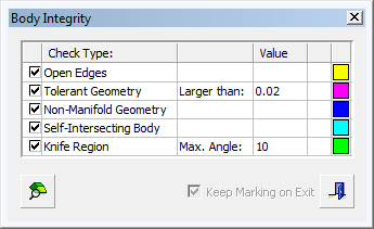
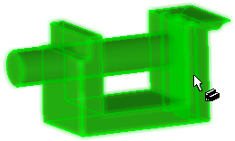
Click the Start AnalysisStart Analysis button to run the analysis and to display the results. Issues are indicated in the dialog by a red X and highlighted on the graphics pane in the defined color, as shown in the following image.
|
|
|
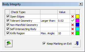
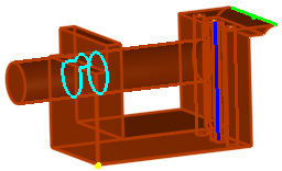
The dialog contains the following controls:
|
|
Start Analysis: Start the analysis. |
||||||||
|
Keep Marking on Exit |
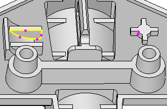
When this checkbox is ON These areas can then be fixed. Once the analysis is completed, the operation to be performed to fix any problematic areas depends on the results of the analysis. You can remove these marks using the functions Hide/Show Analysis MarksHide/Show Analysis Marks or Delete Analysis MarksDelete Analysis Marks. Hide/Show Analysis MarksHide or show the analysis marks created by the last used analysis operation. The markings are areas indicated as problematic during the analysis. To hide or show the results of the analysis, rerun the Hide/Show Analysis Marks function, as required.
Delete Analysis MarksDelete selected analysis marks created by the last used analysis operation. The markings are areas indicated as problematic during the analysis. When invoking this function, all the analysis marks are displayed, even those that were previously hidden. To delete the analysis marks, pick the marks to be deleted and then press OK
The image below shows an example of analysis result marking on an analyzed object.
|
||||||||
|
|
Exit: Exit the operation and close the dialog/task. |

 in the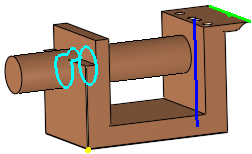

Analysis Options
The following analysis check types are available:
|
Open Edges |
Display all open edges in the selected object. |
||
|
Tolerant Geometry |
Display tolerant edges/vertices which are larger than the defined tolerance value (this information can also be displayed by the Entity Information function). The following parameter is displayed:
Note: If only the Tolerant Geometry option is selected, and if a tolerant geometry was found but it is smaller than the value in the dialog, a message is displayed showing the largest found tolerant value. |
||
|
Non-Manifold Geometry |
Display non-manifold (zero thickness or non-manufactured) edges/vertices. |
||
|
Self-Intersecting Body |
Display all intersections between faces in the selected object. |
||
|
Knife Region |
Display all areas with very sharp edges (up to a defined angle) in the selected object. The following parameter is displayed:
|
Once the analysis is completed, the operation to be performed to fix any problematic areas, depends on results of the analysis.
Click OKOK or ApplyApply
 in the Feature Guide to complete the function.
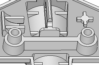
Fix the problematic areas (see the example operation) and re-invoke the Body Integrity Analysis function. If there are no problematic areas, all analysis checks are marked with a green check mark.
