Process Orientation 
Create the forming shape (where the part is gradually unfolded) by defining the appropriate transfer shape over a selected blank. Transfer shapes are used to create the minimum area nesting shapes (to use the minimum material) for the Transfer die. The forming shape includes the selected blank(s) and the chosen transfer shape.
Only one forming shape can be added to the tree, you can edit the part by selecting the function on the side bar.
Usage Example
|
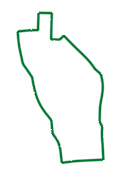
Selected blanks: |
|
Transfer Shapes for the selected blanks: |
||
|
|
Rectangle: |
Parallelogram: |
Miter: |
|
|
|
|
|
|
|
|
|
|
Trapezoid: |
Chevron: |
Arcs: |
|
|
|
|
||
Process
- Click the button in the menu on the right hand side of the graphics pane to open the function.
The Feature Guide is shown here:
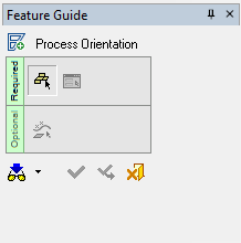
Tip: You can open the Feature Guide at any time by right-clicking the mouse in the graphic display area.
-
Required Step 1: Pick the blank (2D closed wire).
The next step begins automatically.
- Required Step 2: Define the nesting shape and set the parameters to achieve the best utilization.
The following parameters are displayed:
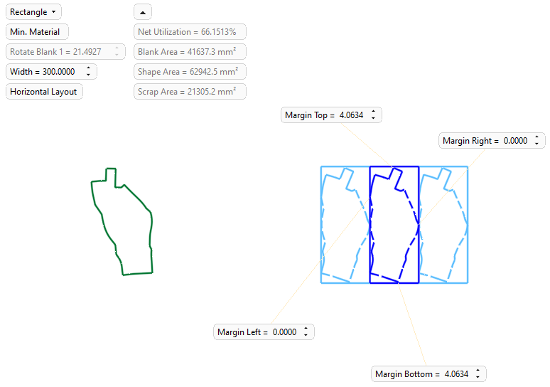
Rectangle
This is a dropdown list that enables you to select the required transfer shape. the following options are available - click Examples below the descriptions to view images:
Rectangle
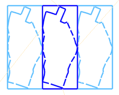
The rectangle shape consists of 4 lines which are perpendicular to each other.
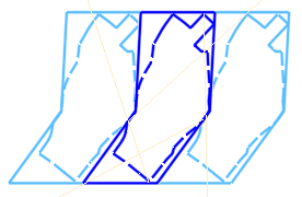
Parallelogram
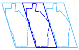
The parallelogram shape consists of 2 pairs of parallel lines.
Miter
The miter shape consists of 3 lines which are perpendicular to each other and 1 line with an angle.
Trapezoid
The trapezoid shape consists of 2 parallel lines and 2 inclined lines.
Chevron
The chevron shape (dart or arrowhead) consists of a concave quadrilateral with one interior reflex angle (>180° but <360°).
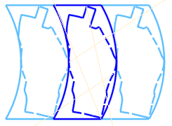
Arcs
The arcs shape consists of 2 parallel lines and 2 arcs with the same radius
Rectangle:
Parallelogram:
Miter:
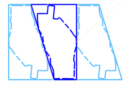
Trapezoid:
Chevron:
Arcs:
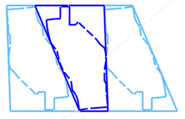
Min. Angle
The minimum angle defined for the shape. This parameter is displayed for all the shapes except for Rectangle.
Default: 0. Valid values: 0 to <90.Auto Radius
This parameter is only displayed for Arc shapes.
This is a toggle option Auto Radius / User-Defined Radius that enables you to either use a system generated auto radius for the arcs or to manually set the radius of the arcs.
Examples:Examples:

If the user-defined radius is too small, a warning message is displayed showing the minimum acceptable radius.
Min. Material / By Angle
This is a toggle option Min. Material / By Angle that enables you to achieve the best material utilization whilst either changing or keeping the current orientation of the blank(s).
Min. Material
Achieve the minimum material utilization by changing the orientation the blank(s), if required, to achieve this.
By Angle
Achieve the minimum material utilization by keeping the current orientation of the blank(s).
Rotate Blank 1
Rotate the first selected blank, as required.
See the note below regarding intersecting blanks.Rotate Blank 2
Rotate the second selected blank, as required.
See the note below regarding intersecting blanks.Width
Set the width of the selected transfer shape.
Examples:Examples:Default width for the transfer shape:
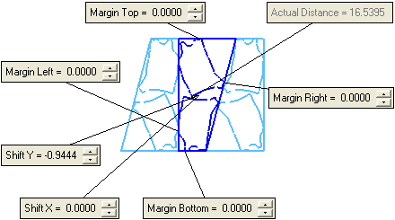
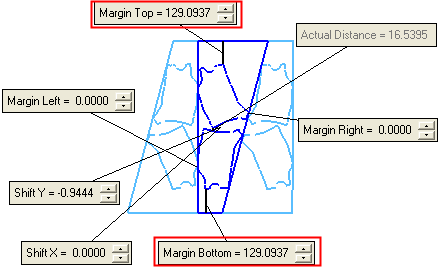
User-defined width for the transfer shape; the difference between the default and the user-defined widths is divided between the top and bottom margins, as shown below:
Horizontal Layout
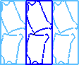
This is a toggle option Horizontal Layout / Vertical Layout that enables you to change the layout to achieve the required material utilization.
Examples:Examples:Horizontal
Layout:Vertical
Layout: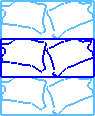
Create Wire
This is a toggle option Create Wire / Create Face that enables you to either create transfer shapes wires or faces.
Examples:Examples:Create
Wire:Create
Face:
In addition to these parameters, the following data information and transfer shape parameters are displayed:
Dropdown Data Information
For each transfer shape selected and for every change to the parameter settings, the dropdown parameters display the following calculated data:
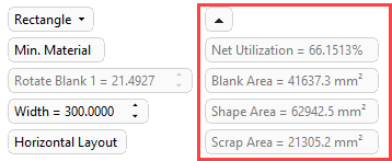
Net Utilization
The net nesting utilization according to the selected transfer shape and parameter settings.
Blank Area
The blank area according to the selected transfer shape and parameter settings.
Shape Area
The shape area according to the selected transfer shape and parameter settings.
Scrap Area
The scrap area according to the selected transfer shape and parameter settings.
Transfer Shape Parameters
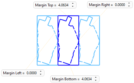
Top, Bottom, Left and Right Margins
The margin settings for each transfer shape.
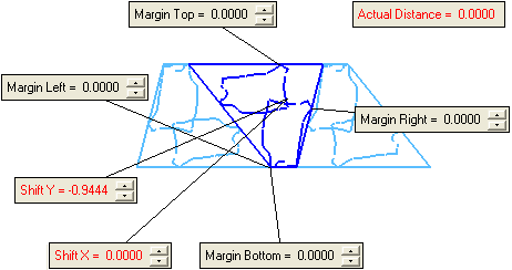
Shift X and Y
The shift X and Y setting for each transfer shape.
See the note below regarding intersecting blanks.Actual Distance
The calculated actual distance between each of the selected blanks within the transfer shape.
Note: If the blanks intersect each other due to the Shift X and Y or Rotate parameter settings, the relevant screen parameters are displayed in red.
Examples:Examples:Intersection has occurred; the relevant parameters are displayed in red:
-
Optional Step 1: Pick additional entities to be transferred.
To transfer addition entities to the new forming shape, pick the required entities from the file containing the blank(s) selected in Required Step 1.
-
Click OKOK
 or ApplyApply
 in the Feature Guide to complete the function.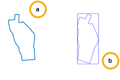
- Blank
- Transfer Shape
When completed, the new Process Orientation feature will appear in the Feature Tree